Flash
.png)
Flash is unwanted excess plastic that forms around parting lines,
mold edges, holes, openings, or other features. It may be caused by
mold wear, excessive injection pressure, insufficient clamping
force, or poor mold alignment.
How the RT-306 can inspect flash
Cameras examine the outside profile, edges, openings, and
parting-line areas of each component and compare the observed shape
with an approved part.
- Excess material around outside edges
- Flash around holes and openings
- Irregular part profiles
- Material extending from the parting line
- Small burr-like plastic projections
Short Shots and Incomplete Features
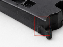
A short shot occurs when molten plastic does not completely fill
the mold cavity. The finished part may have a missing section,
incomplete rib, unfinished edge, partially formed hole, or another
incomplete feature.
How the RT-306 can inspect short shots
Using top, bottom, front, side, angled, or internal views, the
system verifies that critical features are present and fully
formed.
- Missing corners or edges
- Incomplete ribs, tabs, clips, or bosses
- Partially formed holes
- Incorrect outside profiles
- Missing molded details
- Areas with insufficient material
Sink Marks
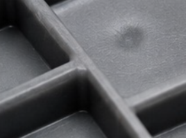
Sink marks are shallow depressions that commonly appear near thick
sections, ribs, bosses, or areas that cool unevenly. They are
generally associated with material shrinkage during cooling.
How the RT-306 can inspect sink marks
With suitable lighting and camera positioning, visible sink marks
can appear as changes in surface shape, reflection, contrast, or
shadow.
- Surface depressions
- Irregular reflections near ribs or bosses
- Localized contour changes
- Cosmetic surface inconsistencies
Detection capability depends on the defect depth, location, part
color, and surface finish.
Warpage and Dimensional Distortion
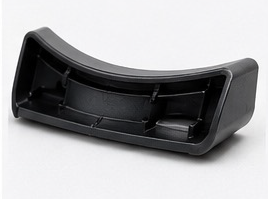
Warpage occurs when a molded component cools or shrinks unevenly,
causing it to bend, twist, bow, or move outside its dimensional
tolerance.
How the RT-306 can inspect warpage
The system measures visible profiles, feature locations, diameters,
widths, lengths, and alignment against programmed tolerances.
- Bent or bowed components
- Incorrect outside dimensions
- Misaligned features
- Out-of-round openings
- Incorrect spacing between molded features
- Parts that do not match the approved profile
Weld Lines and Flow Marks
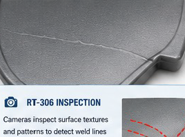
Weld lines form where separate flows of molten material meet inside
the mold. Flow marks, jetting, and similar defects may appear as
lines, waves, streaks, or irregular surface patterns.
How the RT-306 can inspect surface defects
Vision tools inspect selected cosmetic or functional surfaces for
changes in texture, contrast, intensity, and pattern.
- Unusual surface lines and streaks
- Flow patterns near the gate
- Jetting marks
- Visible weld lines
- Localized changes in surface appearance
These applications require controlled lighting and validation using
actual part samples.
Burn Marks and Discoloration
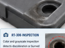
Burn marks can appear as dark, brown, or black areas caused by
excessive heat, trapped air, or inadequate mold venting.
How the RT-306 can inspect discoloration
Color and grayscale inspection tools identify visible areas that
fall outside an approved appearance range.
- Dark or burned regions
- Unexpected color variations
- Black spots
- Localized discoloration
- Surface staining
Performance depends on the visual contrast between the defect and
the surrounding surface.
Contamination and Foreign Material
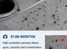
Dust, grease, degraded resin, mixed material, or other foreign
particles may become visible on the surface of an injection-molded
component.
How the RT-306 can inspect contamination
High-resolution cameras examine designated surfaces for unexpected
spots, particles, residue, and color differences.
- Unexpected spots and particles
- Grease or surface residue
- Color differences
- Chips and burrs
- Surface damage
- Missing features
Damaged Features and Scratches
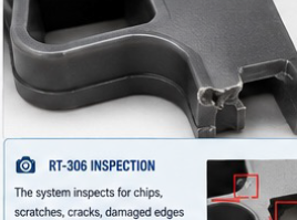
Parts may become scratched, chipped, cracked, dented, or damaged
during molding, ejection, handling, trimming, or transportation.
Insufficient draft may also contribute to scraping or drag marks
during ejection.
How the RT-306 can inspect physical damage
The system examines critical surfaces and molded features for a
wide range of visible defects.
- Chips and visible cracks
- Scratches and drag marks
- Damaged edges
- Broken clips or tabs
- Deformed threads and gate areas
- Missing or partially damaged features
Ejector Pin Marks
.png)
Ejector pin marks are witness marks, indentations, raised
impressions, or discoloration left where ejector pins push a molded
component out of the mold cavity.
These marks may be caused by pin wear, misalignment, uneven ejection
force, or ejector pins positioned in cosmetic areas.
How the RT-306 can inspect ejector pin marks
Cameras inspect designated ejector-pin zones for visible witness
rings, protrusions, impressions, and shading differences.
- Visible witness rings or circular marks
- Raised or recessed pin impressions
- Discoloration or shine differences
- Marks extending above the approved surface plane
- Pin marks outside the approved inspection zone