Common Metal Stamping Defects and How Automated Vision Inspection Detects Them
Metal stamping is one of the most widely used manufacturing processes for producing high-volume precision components. Stamped metal parts are found in automobiles, appliances, electronics, medical devices, aerospace equipment and industrial machinery. The process is fast and cost-effective, but variations in raw material, tooling, lubrication and press settings can create defects that affect fit, appearance, performance and safety.
Traditional manual inspection may identify obvious problems, but it becomes difficult to maintain consistent results when thousands of parts must be examined every hour. Small defects can be overlooked because of operator fatigue, inconsistent judgment or limited viewing angles. Sampling also creates a risk that defective parts will pass between inspections.
Automated vision inspection helps manufacturers examine every part at production speed. By combining industrial cameras, controlled lighting, precision part handling and inspection software, a vision system can identify visible defects, verify critical features and automatically separate nonconforming parts from acceptable production.
What Is Metal Stamping?
Metal stamping is a manufacturing process that uses a press and tooling to shape flat sheet metal into a finished component. Depending on the application, the process may include blanking, punching, bending, drawing, embossing, coining or progressive forming.
Stamped components can range from small clips, washers and electrical contacts to brackets, housings and structural automotive parts. Because these parts are often manufactured at high speed and in large quantities, even a small process variation can produce a significant number of defective components before the problem is noticed.
Common Metal Stamping Defects
1. Burrs and Sharp Edges
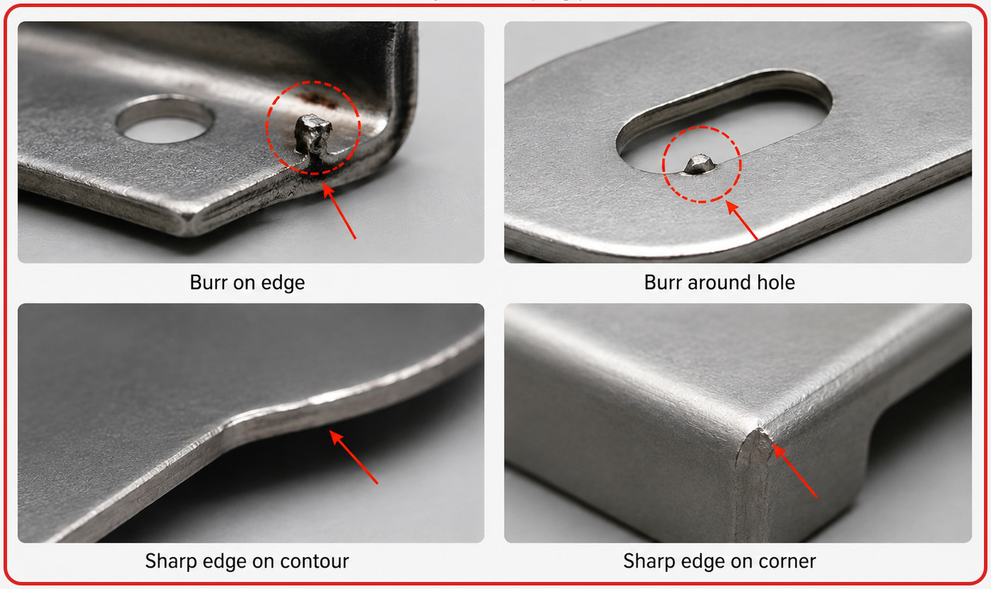
IMPACT: Can cause injuries, damage parts, create poor fits, or lead to assembly issues.
PREVENTION: Proper tool maintenance, optimized clearance, and deburring when required.
Burrs are unwanted raised edges or projections that can develop during blanking, trimming or punching. They are commonly caused by worn tooling, incorrect die clearance, tool misalignment or damaged cutting edges.
Excessive burrs can interfere with assembly, damage mating components or create a safety hazard during handling. A vision inspection system can use directional or backlighting to highlight the part profile and detect irregular edges, excessive material or changes in the expected contour.
2. Cracks and Splits
IMPACT: Can lead to part failure, reduced strength, and safety risks.
PREVENTION: Control material quality, optimize tooling and processes, and avoid excessive stress.
Cracks and splits can occur when the material is stretched beyond its forming limit. Possible causes include insufficient material ductility, sharp tool radii, excessive forming force, poor lubrication or an unsuitable part design.
High-resolution cameras and carefully positioned lighting can reveal visible surface cracks, especially around bends, corners and drawn features. AI-based inspection can also help distinguish irregular crack patterns from acceptable surface texture. However, conventional optical inspection is designed for visible defects; detecting hidden or subsurface cracks may require another technology, such as X-ray or ultrasonic testing.
3. Wrinkles
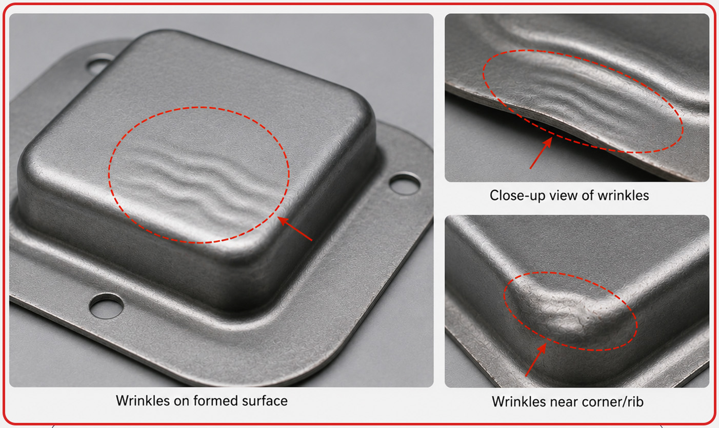
IMPACT: Can affect part appearance, dimensional accuracy, and structural integrity.
PREVENTION: Optimize blank-holder force, lubrication, material flow, and tooling design.
Wrinkling occurs when the sheet metal is compressed unevenly during forming. It is frequently seen in deep-drawn components and may result from improper blank-holder pressure, material flow or tooling geometry.
Wrinkles change the surface profile and can prevent a component from fitting or sealing correctly. Vision systems can identify unusual lines, shadows and texture patterns created by wrinkles. When height information is important, 3D vision or laser profiling can evaluate changes in the part's surface geometry.
4. Scratches, Dents and Surface Damage
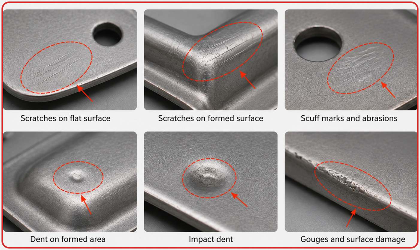
IMPACT: Negatively affects part appearance, corrosion resistance, and customer satisfaction.
PREVENTION: Maintain tooling and handling equipment, apply protective coatings, and minimize contact with hard surfaces.
Stamped parts can be scratched or dented during forming, transfer, bulk handling or packaging. Contaminated tooling, metal fragments, damaged conveyors and part-to-part contact are common causes.
Surface inspection requires lighting selected for the material and finish. Dark-field, diffuse or multi-angle illumination can make scratches, dents and impact marks more visible to the cameras. Inspection software then evaluates their size, location and contrast against the approved quality standard.
5. Incorrect or Missing Holes and Features
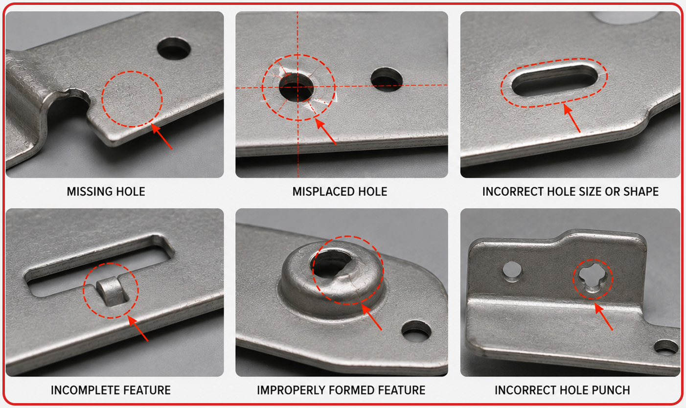
IMAPCT: Can cause assembly issues, poor fit, reduced strength, and functional failure.
PREVENTION: Perform regular tool maintenance, monitor processes, and conduct in-process inspections.
Tool damage, material misfeeding or incomplete press operations can produce missing holes, blocked openings, malformed slots or incomplete tabs. These defects can cause immediate assembly problems or prevent the component from functioning correctly.
Automated vision inspection can verify the presence, number, position and shape of holes and other features. Backlighting creates a clear silhouette, allowing the system to measure openings and compare their geometry with a predefined tolerance.
6. Dimensional Variation
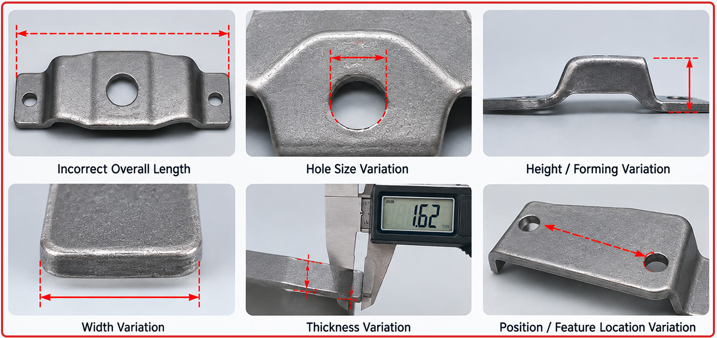
IMPACT: Can cause poor fit, assembly issues, and functional failure.
PREVENTION: Maintain accurate dimensional control, perform regular calibration, and conduct in-process measurements.
Stamped parts must often meet tight dimensional tolerances. Tool wear, press variation, material springback and incorrect setup can affect length, width, diameter, hole spacing and other critical dimensions.
A calibrated vision system can perform non-contact dimensional checks on selected features. It can measure profiles, diameters, distances, angles and feature locations while the parts move through the inspection process. For critical measurements, the system must be designed and validated for the required tolerance, resolution and repeatability.
7. Deformation, Warping and Distortion
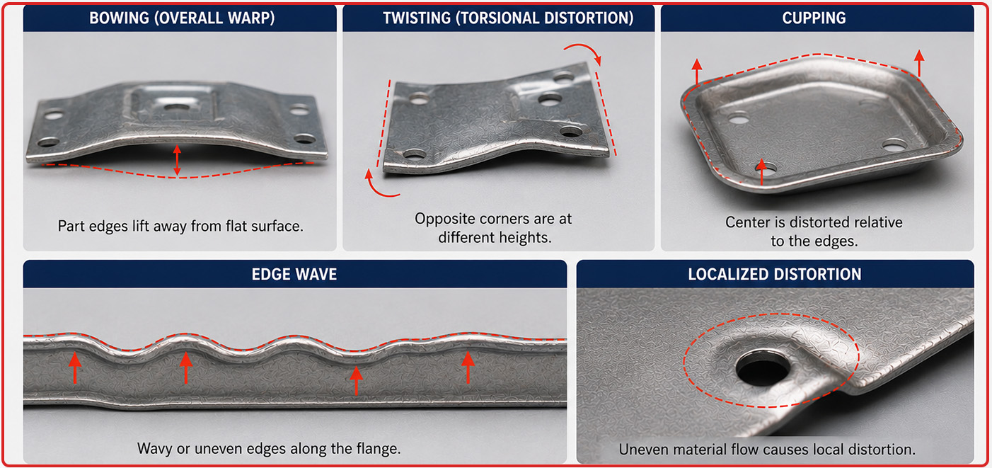
IMPACT: Affects assembly, fit, and appearance and may result in part rejection.
PREVENTION: Optimize tooling design, material thickness, and process parameters, and ensure proper fixturing.
Parts may become bent, twisted or distorted because of uneven forming forces, residual stress, ejection problems or improper handling. Even minor deformation can create problems during automated assembly.
Multiple cameras can inspect the component from different directions to confirm its profile and orientation. For parts whose flatness or height must be verified, 3D imaging or laser displacement technology can detect deviations that may not be visible in a standard two-dimensional image.
8. Incorrect Bends and Springback
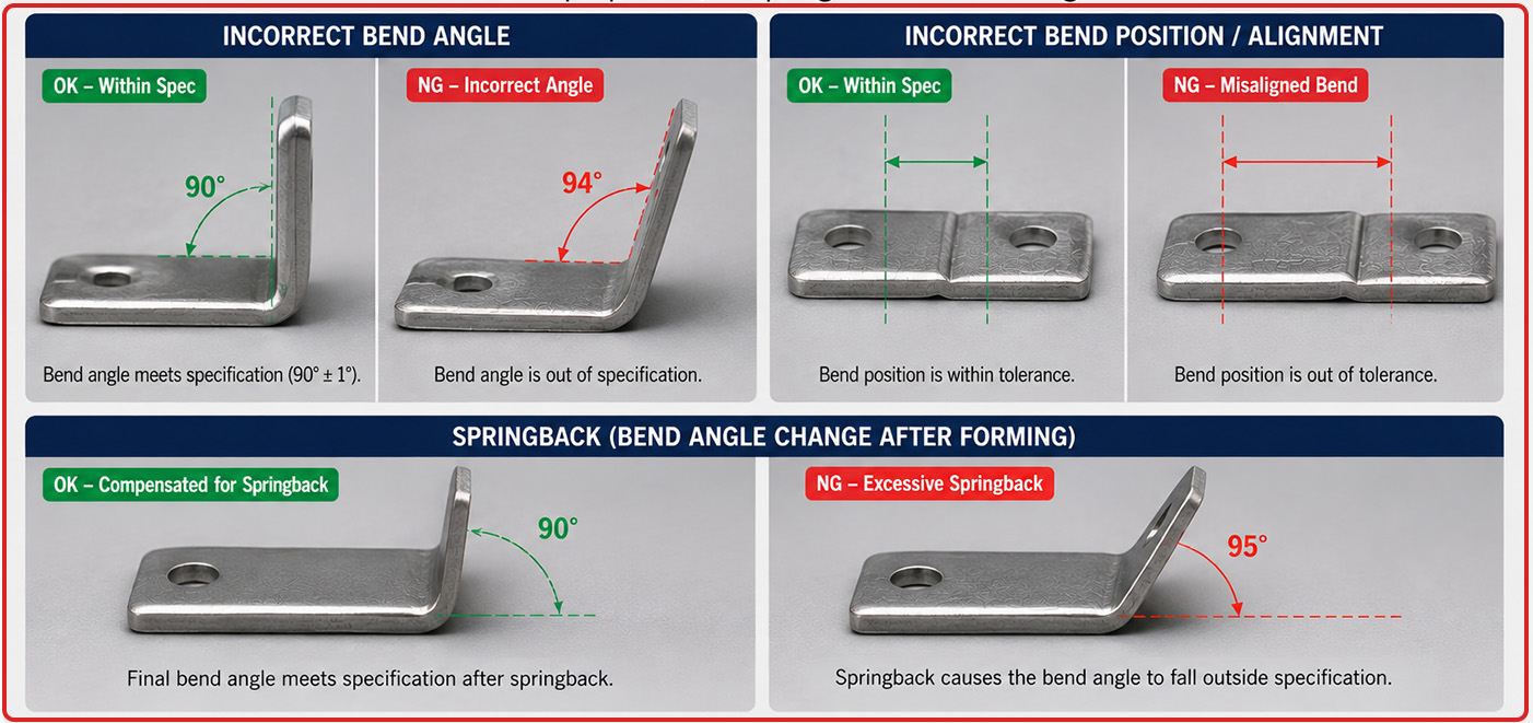
IMPACT: Leads to assembly issues, poor fit, interference, and increased rework or part rejection.
PREVENTION: Ensure proper tooling design, accurate bend deduction, appropriate material selection, and thorough process validation.
After forming, elastic recovery can cause a metal component to partially return toward its original shape. This effect, known as springback, may produce an incorrect bend angle or feature position.
Side-view cameras can measure bend angles, flange height and formed profiles. When a part falls outside the programmed tolerance, the system can classify and reject it automatically.
9. Contamination, Oil and Foreign Material
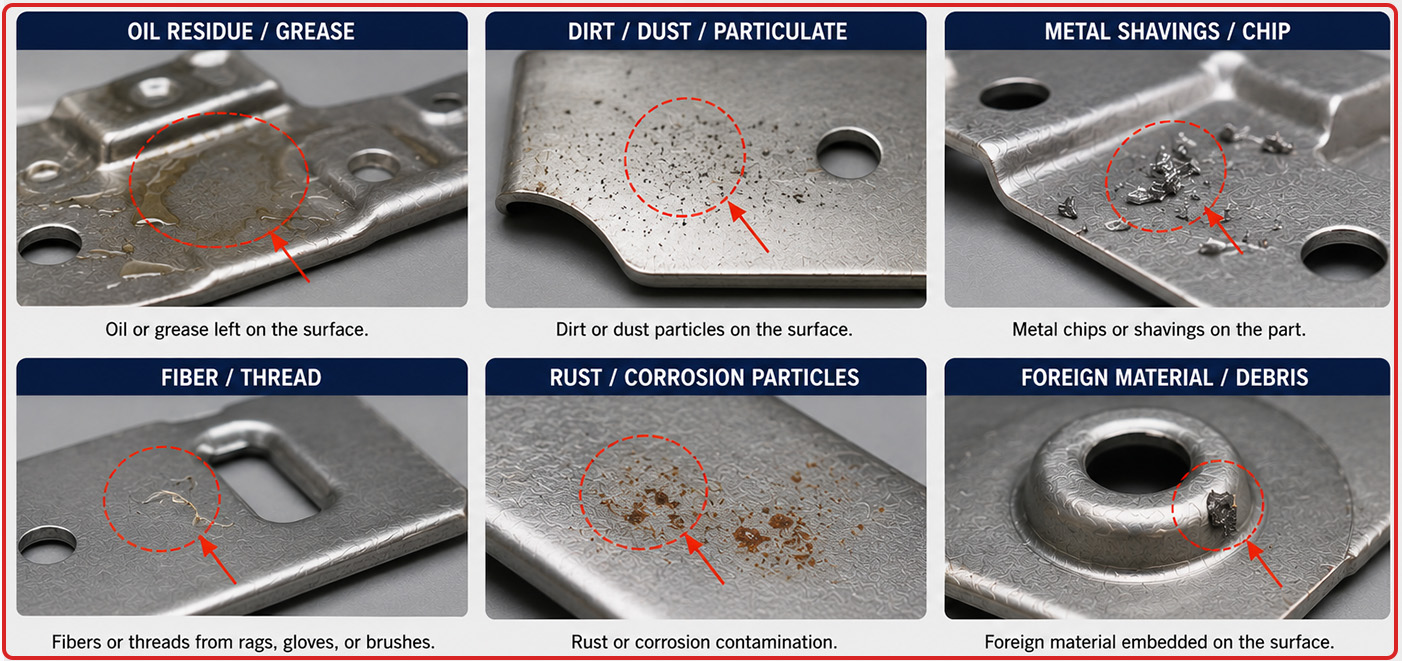
IMPACT: Can cause poor coating adhesion, surface blemishes, wear, corrosion, and assembly issues.
PREVENTION: Maintain clean tooling and work areas, control lubricant application, use filtered air, and implement in-line cleaning and inspection.
Excess lubricant, metal chips, dirt and other contaminants may remain on a stamped component. Depending on the application, contamination can affect coating, welding, sealing, assembly or final appearance.
Vision systems can detect visible contamination when it creates a sufficient difference in colour, brightness or texture. The proper camera, lighting and inspection method depend on the material finish and the type of contaminant being detected.
10. Mixed, Incorrect or Misoriented Parts
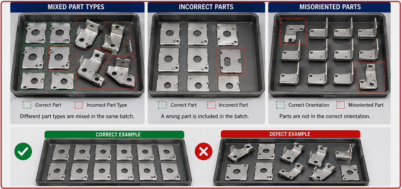
IMPACT: Leads to assembly errors, rework, scrap, customer returns, and production downtime.
PREVENTION: Use vision inspection, part-verification systems, organized trays, and mistake-proofing methods (poka-yoke).
Similar components can become mixed during production, storage or packaging. A wrong part or an incorrectly oriented component can interrupt an assembly line and lead to customer complaints.
Vision inspection can compare each component with the approved part model. The system can confirm its shape, dimensions, feature pattern and orientation before allowing it to continue to packaging or the next manufacturing operation.
How Automated Vision Inspection Works
An automated inspection system is more than a camera. Reliable results depend on controlling the complete inspection process:
1. Part feeding and separation: A bowl feeder, conveyor, linear track or robotic system presents individual parts consistently.
2. Part positioning: The component is stabilized and oriented so its critical surfaces and features can be inspected.
3. Image capture: One or more industrial cameras acquire images under controlled lighting.
4. Image analysis: Rule-based algorithms or AI models evaluate the part against established acceptance criteria.
5. Sorting: Defective components are automatically directed to a reject station, while conforming parts continue to the accepted-part bin or downstream process.
6. Data collection: Inspection results can be recorded to support traceability, reporting and process improvement.
Depending on the component, a system may use area-scan cameras, line-scan cameras, telecentric lenses, backlighting, multi-angle lighting, 3D vision or laser measurement. The correct configuration depends on part geometry, surface finish, production speed, defect size and inspection tolerance.
Traditional Machine Vision and AI Inspection
Traditional rule-based vision is highly effective when a defect or measurement can be defined clearly. It is commonly used to check dimensions, count features, verify hole locations and compare part profiles.
AI-powered vision can be useful when acceptable parts have natural variation or when defects have irregular shapes that are difficult to describe with fixed rules. Examples include scratches, stains, surface damage and inconsistent cosmetic defects.
The best solution may combine both approaches: conventional vision for precise measurements and feature verification, and AI for complex visual classification.
Benefits of Automated Inspection for Metal Stampers
100% Inspection
Automated systems can inspect every presented component rather than relying only on periodic sampling. This reduces the possibility of defects passing between manual quality checks.
Consistent Quality Decisions
Once the acceptance criteria are established and validated, every part is evaluated using the same inspection standard. This reduces variation caused by fatigue or subjective judgment.
High-Speed Operation
Inspection can be integrated with automated feeding and sorting equipment to support high-volume production without creating a manual inspection bottleneck.
Reduced Scrap and Rework
Inspection data can reveal recurring defect patterns and changes in the process. Identifying a developing problem earlier allows the production team to investigate tooling, material or press conditions before more nonconforming parts are produced.
Improved Traceability
Manufacturers can collect inspection counts, rejection data and defect classifications. Depending on system design, reports and images can be linked to production batches to support audits and customer requirements.
Lower Quality-Control Costs
Automating repetitive inspection can reduce dependence on manual sorting while allowing quality personnel to focus on process improvement, root-cause analysis and other higher-value responsibilities.
Important Considerations When Selecting an Inspection System
Before developing an automated inspection solution, manufacturers should define:
• The defects that must be detected
• The minimum defect size
• Critical dimensions and tolerances
• Required inspection speed
• Part size, geometry and material finish
• The number of surfaces and viewing angles
• Acceptable false-reject and escape rates
• Feeding, sorting and packaging requirements
• Inspection-data and traceability needs
• Environmental conditions around the equipment
Representative samples of both acceptable and defective parts are also essential. They help establish realistic inspection criteria, select suitable imaging technology and validate system performance before production deployment.
Automated Inspection Solutions from SORSYS Technologies
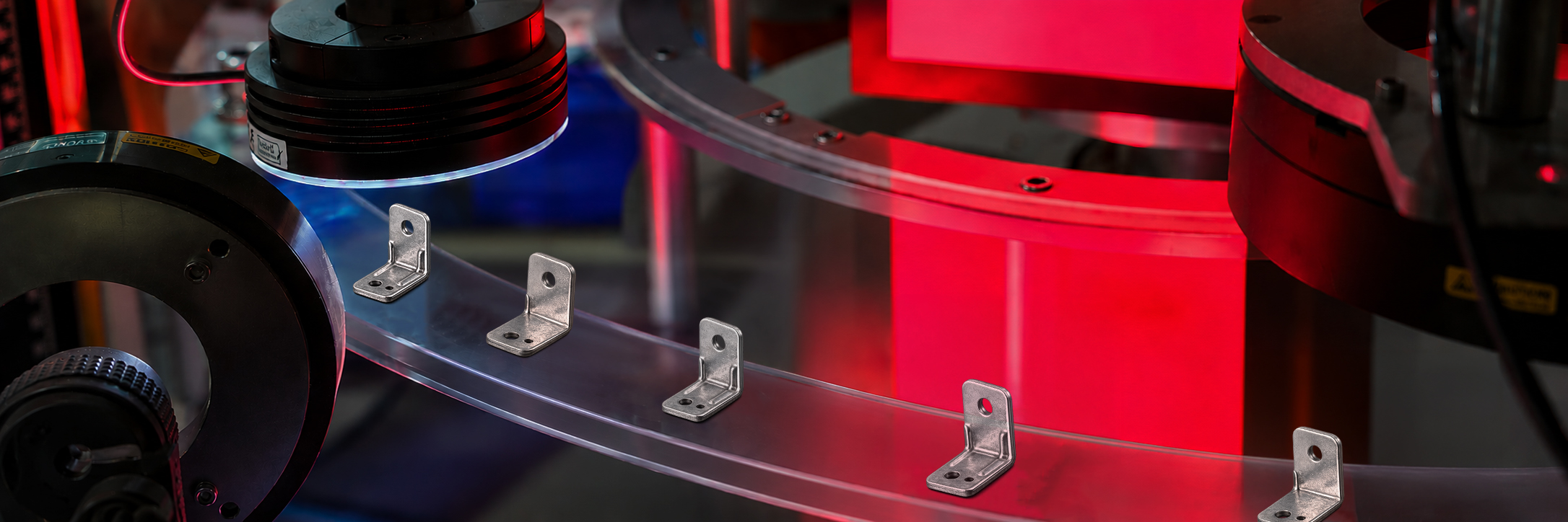
For stamped metal parts, a SORSYS system can be configured to inspect visible surface defects, verify critical dimensions, confirm features and orientation, and automatically separate rejected parts. Inspection results can also provide useful production information that helps manufacturers understand defect trends and strengthen quality control.
Whether you need a standard inspection platform or a fully customized automation solution, SORSYS can develop a system based on your part geometry, defect criteria, throughput and production environment.
Conclusion
Metal stamping is fast and efficient, but worn tooling, material variation and process instability can quickly produce burrs, cracks, wrinkles, dimensional errors and other quality problems. Manual inspection and sampling may not provide the speed or consistency required for modern high-volume production.
Automated vision inspection gives metal stampers a practical way to inspect every presented part, identify visible defects, verify important features and collect actionable quality data. With the right combination of imaging, lighting, handling and software, manufacturers can reduce defect escapes, improve consistency and protect downstream production.
To learn how SORSYS Technologies can develop an automated inspection solution for your stamped metal components, visit sorsys.ca or contact our team for a consultation.